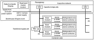
To cover longer distances, different types of technology are used by different providers. A system with a capacitive network (Figure 21) only needs one master modem, which is connected to the three-phase power supply system over a kind of signal line and one or more capacitive bridge units (CBUs). To bridge transformers, transformer bypass units (TBUs) are available.
 |
Figure 21: Schematic diagram of the Dual Band Power Line transmission system from RTE/Lyngsø, H.M. Stein Sohn and ASI (Click on the graphic to enlarge) |
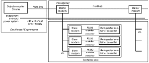
The other system uses a number of master modems which are connected to each other via a field bus (Figure 22). The number of master modems required depends on the network configuration and the distances to be covered. The disadvantage of this is that no more than one master modem may be running at a time. This significantly reduces the effective average data transfer rate in the event of several master modems. In addition, it is fairly likely that some containers are positioned in the catchment area of a number of master modems, meaning that the same data is transferred several times unnecessarily and then needs to be filtered out.
 |
Figure 22: Schematic diagram of the wideband Power Line transfer system (Click on the graphic to enlarge) |