 |
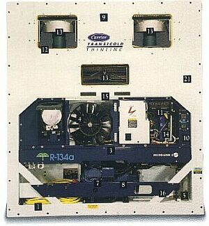
Figure 12: Front end of an integral refrigerated container (Carrier Transicold 69 NT) with components visible |
The expansion valve is attached to the air cooler and accessible through the middle inspection flap.
The condenser of the cold circuit is positioned behind the blue cross bar beneath the condenser fan. The condenser fan sucks air over the coolant compressor through the condenser.
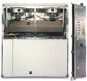 |
Figure 13: Rear of an integral refrigerated container (Carrier Transicold 69 NT) with visible components and side view |
The circulation fans and the air cooler can be seen clearly again in the rear view (Figure 13).
The electric heaters used to heat the container and to defrost the air cooler are also positioned in the air cooler. The drip tray below the air cooler is also electrically heated.
The side view shows the connections for USDA temperature sensors used to measure the temperature of the goods. These temperature sensors are mandatory by the USDA as a proof of insect extermination.
In the event of the container being connected to an on-board water-cooling system, the cooling circuit can be optionally equipped with a water-cooled condenser, as shown in Figure 14.
) |
Click on graphic to enlarge. Figure 14: Cooling circuit of an integral refrigerated container (Carrier Transicold 69 NT) with additional water-cooled condenser |
First, the coolant flows through the air-cooled condenser, but the condenser fan will not operate if water pressure is detected.
Figure 15 shows the cooling water connections to a water-cooled condenser. These couplings are described in ISO 1496-2, but some banana shipping companies use other couplings.
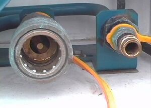 |
Figure 15: Cooling water connections to integral refrigerated containers; return flow - left, supply flow - right |