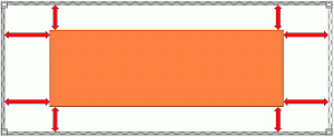
While exactly central placement of the slab in the container is theoretically desirable on load distribution grounds, it is not desirable with regard to the securing measures to be carried out.
All the squared lumber members for lateral and lengthwise bracing ought to be cut exactly to size.
 |
|
| Exact positioning of the slab entails cutting the wood exactly to size. |
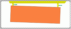
However, if the slab is introduced with a slight offset (which almost always happens anyway when the slab is pushed in), the wooden bracing members need not be cut so exactly. An appropriate number of members ranging in size from the smallest to greatest distance between the slab and the container walls is cut to length and each member can then be "braced in place". The diagrams deliberately exaggerate the offset somewhat in order to clarify the principle.
 |
|
| Slab inserted with offset in order to permit more effective blocking |
If it is assumed that the slab will be exposed in transit to sideways inertia forces amounting to 80% of its normal force and that friction forces of 20% of its normal force will apply, securing must be provided for 60% of the normal force. Since, given a uniform load distribution, the container walls are capable of withstanding 60% of the payload, this value is a good match for the required securing forces.
 |
 |
|
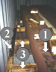
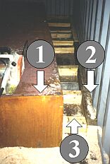
Lateral securing of a slab with 14 cm x 14 cm squared lumber Key to reference numerals: 1 = slab 2 = squared lumber to distribute pressure 3 = squared lumber fixed to container floor for bracing |
||
In this case, 14 cm x 14 cm squared lumber was used. If the price per cubic meter of lumber is identical, twice the length of 10 cm x 10 cm wooden members can be used.
The depth of the members for transferring forces to the container side walls can be improved in this way. If two 10 cm x 10 cm wooden members are positioned in each case against the container side walls instead of the singly positioned 14 cm x 14 cm wooden members, this depth is increased to 20 cm and flexural strength is improved. However, this increases labor costs, because the number of cross braces to be fitted is doubled.
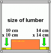 |
Options for use of different lumber sizes |
 |
 |
| Use of different lumber sizes for transferring forces to the container side walls |
The squared lumber should not be nailed to new container floors or those made from plywood and textured coated board. Instead, wooden members may be placed against the slab or fitted between the wooden bracing members. The methods which are generally possible are shown in the following diagrams.
 |
|
| Wooden members fitted against the slab for fixing the cross braces |
 |
|
| Wooden members fitted between the cross braces to fix the latter in place |
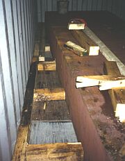
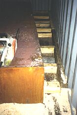
The following is a real example using 14 cm x 14 cm wooden members.
 |
 |
|
securing on left-hand side |
securing on right-hand side |
|
using 14 cm x 14 cm squared lumber |
||
In the lengthwise direction, the container end walls can withstand uniformly distributed inertia forces amounting to 40% of the payload. If 20% friction is assumed, longitudinal forces of up to 60% of the cargo mass can be absorbed.
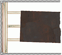 |
Bracing of the slab against the front end wall |
There is no point in using more wooden members than shown as the front end wall would otherwise give way, being the weak point. The maximum securing load of the lengthwise wooden members must accordingly (almost) amount to 0.4 times the container payload.
If part of the transport operation is to take place in Europe by intermodal carriage by road or rail, stresses in the longitudinal direction of 80% to 100% of the slab's normal force must be expected. Given the assumed friction forces of 20%, 60% to 80% of the normal force must accordingly be applied as securing forces in the longitudinal direction. Since the front end wall cannot withstand such forces, bracing of 20% or 40% of the normal force must be provided against the container corner posts, in addition to the 40% against the front end wall.
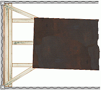 |
Bracing against corner posts with cut "birds' mouths" |
This is implemented with wedge-shaped cuts, or "birds' mouths", in the ends of the wooden members. However, this is only feasible if they are not cut at too acute an angle and the components against which they are to be braced are not too sharp-edged, as there is otherwise a risk that the members will split. Measures which can be taken to counter this problem will be explained below.
| Favorable angle | Excessively acute angle |
Since wood is relatively insensitive to notch effects at right-angles to the grain, one solution is to place additional wooden members between the oblique stays.
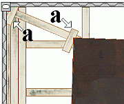 |
Oblique bracing using additional wooden members |
Notches are cut in the additional wooden members (a). The wooden members are placed against the corner posts and the corners of the slabs and the space between is braced with the oblique stays. Since these wooden members are loaded perpendicularly to the grain, for the purposes of calculation they can only be assumed to withstand loads of 30 daN per cm². Directly applied wooden members, which are loaded on the end grain, i.e. parallel to the grain, can be assumed for the purposes of calculation to withstand loads of 100 daN per square centimeter of cross-sectional area.
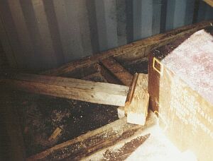 |
V-cut as notch in additional wooden member |
Depending on the particular circumstances, the above variants may also be combined:
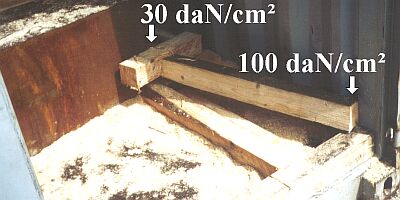 |
|
Different use of wooden members entails other calculations |
 |
|
| Example of wooden members of varying effectiveness |
At (a) on the slab, the V-cut provides an area of 10 cm x 10 cm for loading perpendicular to the grain. Loading capacity is accordingly 100 cm² ≈ 30 daN/cm = 3,000 daN. At the container corner posts, the wooden bracing member is loaded parallel to the grain. However, the forces act on only one third of the member. Loading capacity is 3.3 cm x 10 cm x 100 daN/cm² = 3,300 daN. This securing arrangement can be described as entirely homogeneous.
However, at the real angle of approx. 20°, approx. 94%, or 2,820 daN, of the securing is effective as a lengthwise component, as calculated from the cosine of 20°.
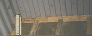 |
Left-hand end bracing |
In the present real situation, the slab, once introduced, was braced first to the sides and then against the front end wall.
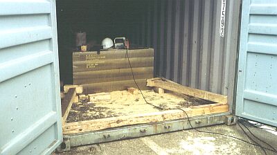 |
|
| Additional transfer of forces to the corner posts |
Subsequently, a squared lumber member was placed in the door area in such a manner that, with the doors closed, the forces are directly transferred onto the door leaves with lengthwise wooden members which are yet to be put in place. In addition, oblique stays were placed against the corner posts.