Coils in 20' box containers: winding axis lying lengthwise
General information and options
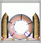
Introducing coils into open-top containers causes no difficulty. When ordinary box containers are used special equipment or precautions must be used during cargo handling.
 |
|
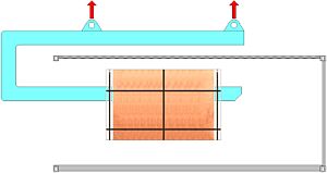
Introducing coils into a box container using a special C hook |
Forklift trucks can only be used for direct handling of low mass coils of up to approx. 2.5 metric tons. Heavier coils must be pushed into the container. This requires special working methods in order to prevent tearing of the strapping and to avoid bruising the coils.
Coils can be pushed in if auxiliary materials are used which have a high coefficient of sliding friction on the coil side and a lower coefficient of sliding friction on the outside. If this is the case, the materials stick to the coil and are "entrained" as the coil is pushed in.
Suitable cradles must be prepared before loading is begun.
 |
|
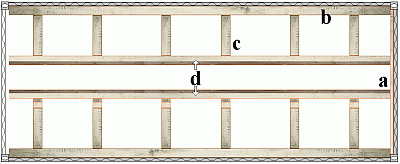
| Coil cradle - plan view |
 |
|
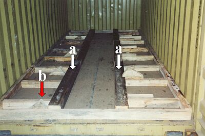
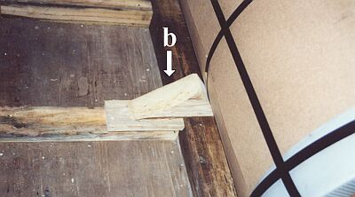
Using boards or planks, the front end wall is braced (a) flush with the corner posts up to twice the height of the lumber size used. Squared lumber (b) is laid down at the sides of the container to distribute pressure. Depending upon the number of coils to be loaded and their mass, crosspieces (c) are laid at right angles to the side beams. Wedge members (d) are then laid lengthwise.
N.B.: Since the coils are subsequently to be lashed, the lashing points must remain accessible. Should these be located under the lengthwise beams (b), the necessary lashing means can be attached to the lashing points before the wooden members are laid. The lengthwise beams (b) can then be placed on small boards.
 |
|
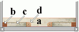
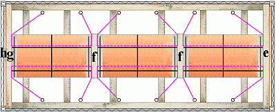
| Loading and interim securing of coils - plan view |
 |
|
| Loading and interim securing of coils - cross-section |
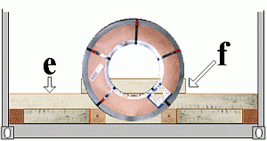
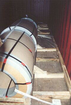
Before loading begins, a beam (e) is laid crosswise in front of the boards or planks (a) and the corner posts. This beam (e) lies on the lengthwise members (b) and (d). The first coil is laid against this crosswise beam (e). A shorter beam (f) acting as a spacer relative to the next coil is laid crosswise over the wedge beams (d) and the second coil is loaded against it. The same method is used for the third coil. (f) is at the level of (e) and is only shown higher to make it more visible.
 |
|
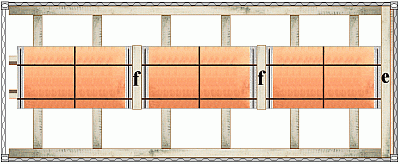
| Three coils: blocked and lashed - plan view |
 |
|
| Three coils: blocked and lashed - cross-section |
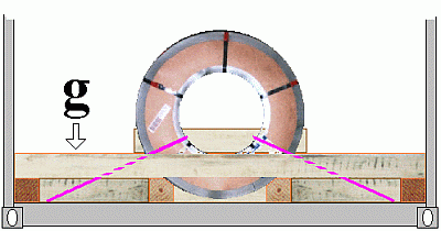
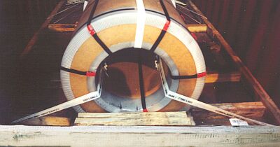
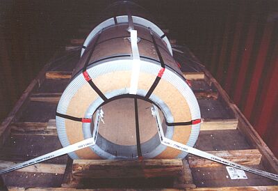
Once the last coil has been placed, the remaining gap towards the container door is filled with squared lumber (g) and boards or planks (h). Each coil is secured with two loop lashings passed through the eye. These lashings secure the coils laterally and prevent them from popping vertically out of the wedge beams under dynamic loads.
Since some of the lashing points are unfavorably located, as is often observed in practice, the resultant angle of the lashings means that they provide, for example, only 60 - 70% of their maximum securing load.
 |
 |
||
| Additional securing
by bracing beams |
Additional securing with
airbags |
With larger diameter coils, the flanks of the wedge beams must be at a different angle.
If lashings are inadequate due to unfavorable lashing angles or relatively weak lashing points, additional securing can be provided with shoring beams. As shown in the diagram, the shoring beams are located against the top side rail and, to prevent slippage, between the container corrugations. The greater the web height of the beams, the greater is the flexural strength. In order to save materials, half-size lumber, such as 6 cm x 12 cm or 8 cm x 16, should be preferred.
If airbags are to be used, they must be used in sufficient numbers for the forces to apply uniformly over the container walls. However, no significant gain can be expected because, although the container walls can be loaded with 60% of the payload, the majority of the forces are already transferred into the side walls via the wooden crosspieces on the floor. The most important factor, however, when using airbags is that the gaps in the stow must not be excessively large. Experience has shown that gaps of 30 cm should be regarded as the maximum, but smaller gaps are better. The shape of the cargo should moreover be as uniform as possible, as airbags are only able to conform to the shape of the cargo to a limited extent.
Example: Three coils in a 20' box container
 |
|
| Inadequate cradle for accommodating coils |
The lengthwise wooden members (a) are not chamfered. If, as should be the case, the coils rest clear of the floor, they will bear down directly on the two longitudinal edges. Wedge beams should have been used. The large number of wedges would indicate that they are intended to provide sideways securing. However, they have not been correctly cut for this purpose.
 |
|
| Incorrectly cut wedges - nails will have to be driven into the end grain |
The wedges have been cut so that the nails will have to be driven into the end grain. This will result in the wedges splitting, at the latest when exposed to impact in transit . The wedges rely solely on the nail shear forces. High maximum securing loads cannot be expected.
 |
Inadequate lateral securing with wedges |
Two wedges were placed by the front coil (the one by the front end wall). Only one wedge was placed by each of the middle and rear coils, the latter closest to the door.
 |
|
| Inadequately applied cargo securing |
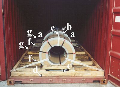
No wooden members were fitted to provide a tight fit between the front end wall and the first coil (a). There is likewise no squared lumber to provide a tight fit between the coils and the door, (b) and (c). The squared lumber (d) is performing no useful function. The coils are bound together with single-use webbing belts (e). This type of unitization provides no additional securing action. The loop lashings (g) are holding the front and middle coils together, while the loop lashing (f) is holding the middle and rear coils together, latter being closest to the door.
 |
|
| Improved securing with squared lumber members fitted crosswise |
The shortcomings in the lengthwise securing can be eliminated by fitting squared lumber in the gaps. The crosspieces at the front end wall and the door have to transfer compressive forces over a large area. The green light only relates to lengthwise securing.
 |
|
| Loop lashings with single-use webbing belts |
It is essential to take note of the labels on the belts or other information from the manufacturer. The maximum securing load should be assumed to amount to at most 70% of the breaking load, or better still only 50%. Note the uniformity. The belts shown in the picture have a higher maximum securing load than the lashing points. Moreover, the lashing points are round and thus not suitable for fastening belts. Shackles should be used to join the belt to the lashing point, with the webbing belts being passed over the shackle pin.