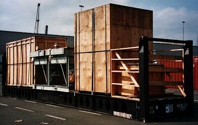
Cases, some overheight and slightly overwidth, together with an overwidth plant part on a 40' flatrack
 |
|
| Export cargo on a 40' flatrack |
The left-hand case is approx. 10 cm from the end wall of the flatrack and is secured with three tie-down lashings, the plant part and the case packed to the right thereof being secured with two tie-down lashings. The smaller wooden case is blocked into the lengthwise bracing.
 |
|
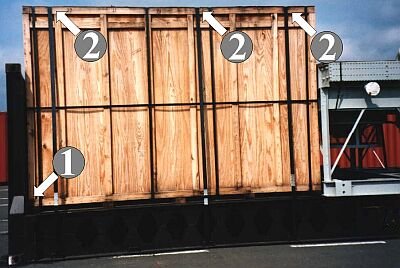
| Inadequate securing of the long wooden case |
The gap at (1) could easily have been filled with 10 cm x 10 cm squared lumber. Steel strapping tie-down lashings tensioned over wooden edges (2) cut in, lose their pretension and are then only capable of providing a limited degree of securing. Securing with case restraint shoes at floor level is advisable. The steel strapping tie-down lashings could remain as securing against tipping, if segments of rubber tire were laid under them. Heavy-lift steel cornerpieces can prevent cutting into wooden members. However, these measures do not alter the fundamental disadvantage of steel strapping, i.e. its low elasticity.
 |
|
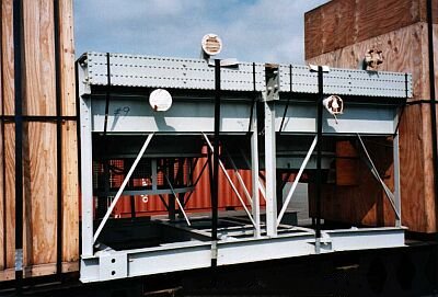
| Inadequately secured plant part |
The two tie-down lashings alone cannot secure the cargo in the long term, given that steel is here stowed on steel. The plant part is freely movable sideways in the tie-down lashings.
The plant part should as a bare minimum have been placed on friction-enhancing material, or at the very least wooden boards.
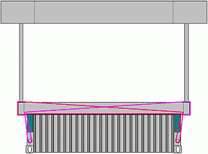
| Right and below: possible securing using loop lashings |
 |
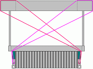 |
Loop lashings have already been suggested so often in this section that this option should generally be considered and assessed for possible ways of implementing it. However, another securing method is feasible:
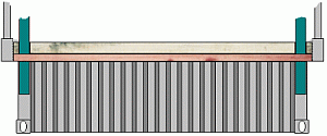
Since the base frame of the plant part projects over the sides of the flatrack, internal bracing is an option. For this purpose, short steel profiles corresponding to the stanchion cross-section are inserted into the stanchion pockets. If the flatrack has very low stanchions, these may of course be used.
 |
|
| Bracing against steel profiles inserted into the stanchion pockets |
 |
 |
|
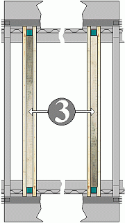
| Producing internally acting wooden bracing - steps 1 to 3 |
||
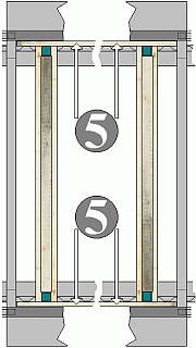
Wooden beams, for example 6 cm x 8 cm beams, are laid on their edges to the left and right of the inserted steel profiles or stanchions (1) and attached to the flatrack floor (2). The length of the beams must be matched to the internal dimensions of the structure to be secured, but they do not have to be cut absolutely exactly to size, since they are just auxiliary wooden members. A squared lumber member (3) cut precisely to length is fitted onto each pair of beams between the steel profiles or stanchions and fastened to the beams. Each squared lumber member is intended to allow utilization of the strength of two profiles or stanchions. This step can be omitted if the cargo items are light.
 |
 |
|
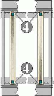
| Producing internally acting wooden bracing - steps 4 or 5 |
||
Squared lumber pieces (4) are fitted precisely in the crosswise direction or squared lumber is fitted in the lengthwise direction (5) between the internal edge of the plant part and the external edge of the steel profile or stanchion and in each case fastened to the beams beneath.
The squared lumber at (4) is loaded against the end grain, i.e. end on to the grain. A maximum securing load of 400 daN per square centimeter of effective supporting surface area may therefore be expected. The squared lumber at (5) is loaded perpendicularly to the grain. In this case, an effective supporting surface area of only 30 daN per square centimeter can be expected.
 |
|
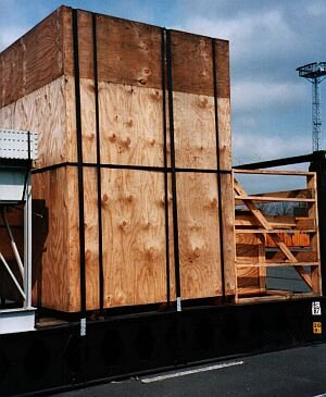
| Wooden case secured inadequately in the crosswise direction |
The statements already made in relation to the longer case also apply to securing of this taller case.
 |
|
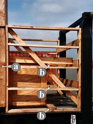
| Lengthwise case securing in need of improvement |
Positive comments first: The bracing for the tall case has been fitted in such a way that the plate action of the sides of the case (a) is exploited. The small case, positioned in the stowage gap, is only secured by wooden fixings (b), i.e. planks nailed on crosswise. The diagonal boards serve to stabilize the structure.
 |
|
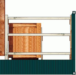
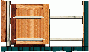
| Expertly braced cases |
The tall case is braced by horizontal wooden members, which lie on the transverse boards of lattices. The lattice in front of the case consists of two vertical squared lumber members and three transverse boards, while the lattice in front of the flatrack end wall is made from two vertical and three transverse boards.
 |
|
| Securing of the small case |
The small case is secured by building a small lattice from two vertical and two transverse boards and positioning it against the case end wall. Squared lumber is fitted between this lattice and the one against the flatrack end wall. To provide lateral securing, squared lumber is additionally threaded through and fitted next to the case.