1,600 kg wooden case on a 20' flatrack
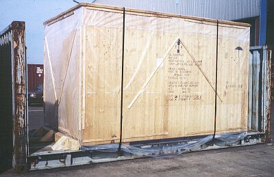
Overheight moisture-sensitive case on a 20' flatrack
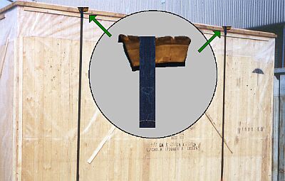
The features of this stowed case which are immediately noticeable are the "Top" marking and the umbrella symbol. It would be desirable for this case to have been provided with the standard "Keep upright" symbol, in other words two upright arrows which are positioned at the top right and on an adjacent surface of the case, together with the umbrella symbol for "Keep dry".
It is unlikely that the 0.2 mm thick (200 μ) film membrane additionally applied to the box would be enough to keep it dry for the entire voyage. Because of its overheight, the flatrack is best transported on board ship in a stowage space in the top tier below deck. However, it is more likely that the flatrack will be stowed on deck. It is unlikely that the film will be able to withstand the full rigors of a voyage, or indeed of onward carriage by railroad or truck.
Only passing mention will be made of the fact that the marking complies only in part with the standards; however, each of these shortcomings is relevant in the broadest sense to "cargo safety".
 |
|
| Sensibly and correctly affixed handling symbols |
| According to its markings, the case has a gross weight of 1,600 kg. |  |
|
| Gross weight of the case |
The securing forces required according to the CTU packing guidelines are relatively simple to calculate, although the coefficient of sliding friction is incalculable. Because it is probable that the case will be loaded on deck or will be uncovered during onward transport, occasional precipitation must also be anticipated. Therefore, a coefficient of sliding friction of μ = 0.2 is assumed for the example, i.e. a friction value of 20% is used for calculation purposes. All numerical values are stated in decanewtons (daN).
The securing forces required for a voyage during which the flatrack is stowed "fore and aft" (fore and aft stowage) are calculated as follows:
| Normal force of the package | Acceleration forces in | Friction forces, where coefficient of sliding friction μ = 0.2 | Required securing forces | ||
| Lengthwise at 0.4 g | Crosswise at 0.8 g | Lengthwise | Crosswise | ||
| 1,600 | 640 | 1,280 | 320 | 320 | 960 |
In the unlikely event of the flatrack being stowed athwartships on board ship, the following securing forces would be required:
| Normal force of the package | Acceleration forces in | Friction forces, where coefficient of sliding friction μ = 0.2 | Required securing forces | ||
| Lengthwise at 0.8 g | Crosswise at 0.4 g | Lengthwise | Crosswise | ||
| 1,600 | 1,280 | 640 | 320 | 960 | 320 |
The case will probably be taken off the flatrack at the port of destination and carried onwards conventionally. However, to be on the safe side, it should be assumed that the case remains on the flatrack for onward carriage. It is not known how the flatrack would be positioned on a truck for road transport, but for rail transport it is assumed that no switching stresses arise. Under these conditions, the securing forces would be calculated as follows:
| Normal force of the package | Acceleration forces in | Friction forces, where coefficient of sliding friction μ = 0.2 | Required securing forces | ||
| Lengthwise at 1.0 g | Crosswise at 0.5 g | Lengthwise | Crosswise | ||
| 1,600 | 1,600 | 800 | 320 | 1,280 | 480 |
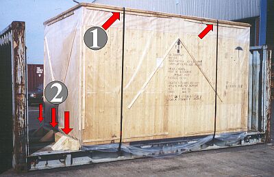
With the selected securing method using tie-down lashings (friction loops) (numeral 1 in the Figure), the stowage direction of the flatrack is irrelevant, since tie-down lashings act in all directions. For the assumed coefficient of sliding friction of μ=0.2 and required securing forces of 960 daN for example, a total pretension of 4,800 daN would be necessary for the voyage (960 daN � 0.2 = 4,800 daN). If two tie-down lashings are present, each would have to be pretensioned to 2,400 daN and be capable of retaining this pretension through the voyage. In the example illustrated, steel strapping was used for the tie-down lashings, and was tensioned only over the top edges of the case. Even if it cuts into the lumber by only a few millimeters as the result of a jolt during transport, all pretension would be lost and the tie-down lashings would no longer have any securing effect on the case.
 |
|
| Shortcomings in case securing |
The cohesive resistance of the nails in the wedges used for cargo securing (numeral 2 in the Figure) should be estimated at approx. 100 daN per nail due to the small plank thickness of the flatrack floor and the resultant low penetration depth. If there are three retaining nails hammered in vertically per wedge, the lengthwise securing forces produced by the three wedges amount to 900 daN. If the effect of the tie-down lashings is ignored, there is a slight cargo securing deficit.
Given the low case mass of 1,600 kg, steel strapping tie-down lashings can also be used if it is ensured that the calculated pretension can be maintained throughout the voyage.
This may be ensured by combining the steel strapping with a material with good recovery. The use of automobile tire segments provides an economic solution.
 |
|
| Tire segment for improving elasticity and maintaining pretension |
If it is assumed that the tools and lashing points used allow at most 1,500 daN of pretension per tie-down lashing, a securing force of around 300 daN may be achieved per tie-down lashing for a coefficient of sliding friction of 0.2. It is accordingly possible to achieve the securing forces required for maritime transport with four steel strapping tie-down lashings, while the forces required for onward carriage by road or rail would be covered with five.
 |
|
| Producing simple bracing from wooden boards and squared lumber beams |
In general, securing with wedges should be avoided with cases. If a tight fit is required in the lengthwise direction, much can be achieved with wooden bracing. For a case with a low mass of 1,600 kg, such wooden bracing is simple and cheap to produce. One narrow (1) and one wide board (2) are nailed together in each case in such a way that a step-shaped double board is obtained. The height of the narrow board must match the height of the case props (3). Bracing made from simple beams (4) is fitted - cheap 6 cm x 8 cm softwood is quite sufficient.