Used plant part on a 40' flatrack
 |
||
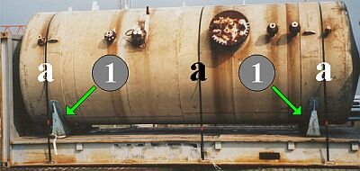
| Inadequately secured boiler on a 40' flatrack | ||
The steel cradles (1) have enormous potential for providing safe securing. However, they do not provide adequate cargo securing when used in combination with these three steel strapping tie-down lashings.
 |
||
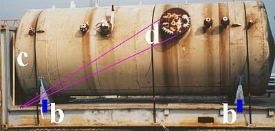
| Adequately secured boiler | ||
Full lateral securing can be achieved by welding to the cradles angles and/or guide plates (b) which engage over the edge of the flatrack.
For lengthwise securing in the one direction, the boiler is packed tight against the front end wall and/or any small gaps are filled with lumber (c).
To prevent movement to the other end wall, a lashing is guided obliquely relative to the direction of movement on each side (d). The tie-down lashings then assume the function of direct securing in the vertical direction. If a material with good recovery were positioned between the steel strapping tie-down lashings and the boiler, the tie-down lashings could produce additional securing forces in all horizontal directions due to their pretension. The numerical value of these securing forces would be even greater if friction-enhancing material were laid or had been laid between the steel cradle and the flatrack floor.
 |
||
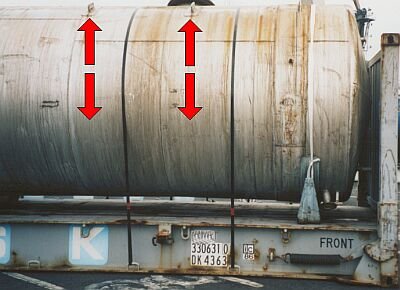
| Alternative securing options | ||
It should have been checked whether direct lashings would have met the securing objectives better than the tie-down lashings.
Used plant parts on a 40' flatrack
 |
||
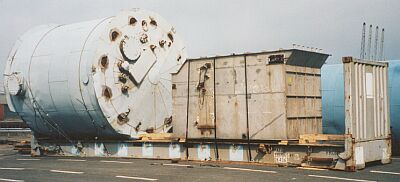
| Inadequately secured plant parts on a 40' flatrack | ||
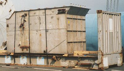
Neither the left-hand, boiler-like plant part nor the right-hand receptacle is properly secured:
 |
||
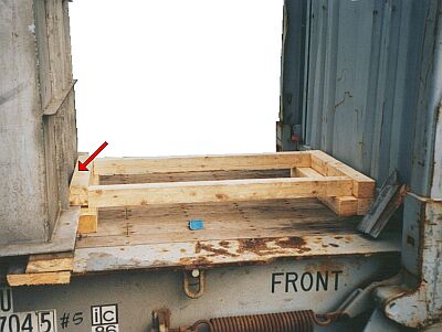
| Deficiencies in the wooden bracing against the front end wall | ||
The crosspiece lying against the item of cargo is too short and has an effective cross-sectional area of only a few square centimeters. The gaps between the item of cargo and the crosspiece need to be filled.
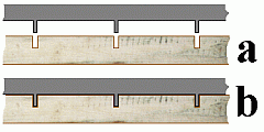
However, it is better and quicker to cut slits in an additional crosspiece with a saw (a), so that the metal webs on the receptacle can lie flush against the lumber (b).
 |
Options for eliminating deficiencies |
 |
||
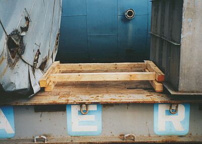
| Deficiencies in the wooden bracing between the items of cargo | ||
The wooden bracing between the items of cargo exhibits the same shortcomings as that against the front end wall.
The bracing lying against the right-hand receptacle can be modified as described above. Against the left-hand receptacle, the upper crosspiece must be long enough to cover the boiler edge.
 |
||
| Inadequate securing of the receptacle | ||
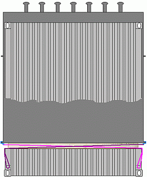
The lateral securing of the receptacle itself is inadequate, consisting as it does of only three tie-down lashings.
 |
||
| Lateral securing by direct lashings using claws | ||
 |
 |
|
| Use of claws for lateral securing - detail | ||
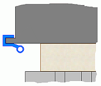
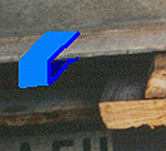
A good way of providing lateral securing is to use claws, which can be applied to the base profiles of the receptacle.
The tie-down lashings are retained to provide vertical securing and to secure against tipping.
 |
||
| Inadequate securing of a used plant part | ||
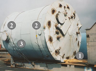
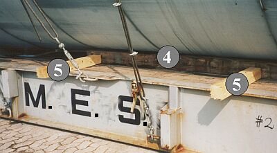
The wooden bracing (1) between the two items of cargo has already been criticized. The lashings (2) act solely as tie-down lashings due to friction forces and as direct lashing against upwards motion. They cannot provide additional lateral securing because of the overwidth. Although the direct lashing (3) could hold the boiler to a degree in the lateral direction, a longitudinal component also acts in the direction of the bracing. The wire lashings do not comply with the instructions given above, being nonuniform.
 |
Inadequate lateral securing in the base area |
On this side, only one beam is positioned lengthwise in the base area and attached with nails.
 |
||
| Inadequate lateral securing with wooden fixings | ||
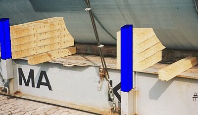
On the other side, two wooden fixings (5) are positioned crosswise in addition to the laterally fitted squared lumber (4) and are fixed with a few nails.
 |
||
| Improvements to lateral securing | ||
The stanchion pockets provided allow adequate lateral securing of the boiler with wooden members and relatively short case profiles or steel beam ends. For this to be feasible, however, the boiler walls have to be able to withstand this load. If they can, then the tie-down lashings once again seem sensible and no space is left for the direct lashing (3) to the flange shown in the third last picture - under these new conditions, it may be dispensed with.
Plant part on 40' flatrack
 |
||
| Above and right: inadequately secured plant part on a 40' flatrack |
 |
|
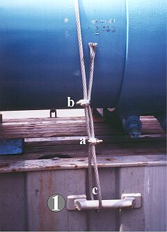
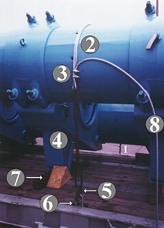
In the arrangement shown, the plant part was secured by three lashings. A 16 mm diameter steel cable was attached to a lashing bar (1) on the one side of the flatrack with one correctly applied (a) and one incorrectly applied wire clip (b). From there, the cable was passed round the component (2) with a round turn, i.e. an additional winding, and attached to one end of a turnbuckle (4) with two incorrectly applied wire clips (3). The other end of the turnbuckle was attached by a shackle (5) to the lashing point (6) recessed into the floor of the flatrack. In addition, the shipping package was fixed in the floor area of the flatrack by three nailed-down wedges (7) on each side. The wedges were all incorrectly cut.
The wire lashings were nonuniform for various reasons. The lashing point at (1) has a maximum securing load of approx. 7,500 daN, while that of the lashing point at (3) recessed into the flatrack floor is only approx. 4,000 daN. The steel cable itself has a maximum securing load of something over 10,000 daN, but only 5,000 daN at most are utilizable if, as is the case here, only two wire clips are applied in each case. The perceptible pretension at the turnbuckle (4) was very high. However, because of the round turn, not very much of this was applied to the lashing point (1), which is clear from the round shape of the wire loop at (c). Added to this waste of resources due to nonuniformity is the loose end of the wire (8), which was more than 2 meters long and signifies additional waste of material.
It must be pointed out that this flatrack had six integral lashing belts each with maximum securing loads of 2,000 daN guided over lashing reels, albeit on one side.
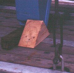 |
Incorrectly cut wedge |
Since the wedge has been incorrectly cut or used, the nails have been knocked into the end grain. Even here at the point of departure it is clear that the wedge is splitting and the same could be said for all the other wedges.
 |
||
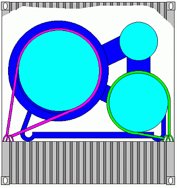
| Effective lateral and vertical securing by loop lashings | ||
Loop lashings, with their ends applied to separate lashing points, would have allowed adequate transverse and vertical securing. Full lengthwise securing would have been readily possible if the end feet had been braced against the end walls of the flatrack. The most sensible option economically would be to use the lashing belts of the integral lashing reels on the one side as loop lashing and to secure the other side with prefabricated lashing belts, which must have an identical maximum securing load.