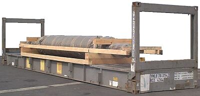
Example: Plant part in a wooden cradle on a 40' collapsible flatrack
 |
|
| Plant part in a wooden cradle - not yet secured |
The roll-like plant part lies in a cradle attached to the forwardly and rearwardly tapering ends by threaded rods in the form of "pipe clamps". Interconnection is effected only by the two lengthwise wooden members, which are fitted laterally at the bottom. The upper frame consists of two lengthwise wooden members and two wooden crosspieces, which are simply nailed. This alone is not adequate to hold the part secure in the cradle.
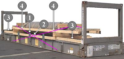
This picture shows how satisfactory securing can be achieved:
 |
|
| Plant part in a wooden cradle - secured |
The flatrack used being one with stanchion pockets, three stanchions (1) should be inserted on each longitudinal side (merely indicated in the picture). If no stanchions are available, appropriate steel profiles or steel girders should be used. It is absolutely necessary for three squared lumber members to be fitted in the base frame transversely relative to the stanchion positions (2), so that the cradle is stabilized in the base area and held secure in the crosswise direction by the stanchions or steel profiles . Corresponding lengthwise securing of the cradles in the base area should be achieved by using longitudinally positioned squared lumber members (3). The wooden members illustrated need to be conformed to the weight of the package and possibly X-braced with boards. The top crosspieces of the "pipe clamps" need to be fixed lengthwise with loop lashings (4) in such a way that the plant part is secured in its cradle.
If the factory-fitted cradle is studied carefully, it will become apparent that other options for lengthwise securing might be possible, provided that information about the loading capacity of the plant parts is provided by or can be obtained from the manufacturer.
 |
|
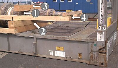
| Cradle of the package at one end |
 |
|
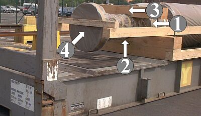
| Package cradle viewed from other end |
If the bearing (1) is loadable in the lengthwise direction, the crosspieces (2) and (3) could be reinforced by means of horizontally fitted oblique bracing against the corner posts of the flatrack. If the shaft and shaft flange (4) were loadable in the lengthwise direction, oblique bracing could be positioned from that point horizontally against the corner posts of the flatrack.
 |
|
| Diagram showing the principle of oblique bracing between the bearing struts (a) or the end flange (b) and the corner posts in flatracks without a fixed end wall |
 |
"Bird's mouth" in the wooden members for the corner posts |
So as to be able to transmit the force to the corner posts, so-called "birds' mouths" have to be cut into the squared lumber members which bear on the corner posts.
When using flatracks with fixed end walls, horizontal bracing could be fitted against the end walls of the flatrack, using wooden members for pressure distribution.
 |
||
| Diagram showing the principle of horizontal bracing between the bearing struts (a) or the end flange (b) and the flatrack end wall |
||
It should be possible to prevent damage by simultaneously securing both static and rotating parts of the plant. Individuals involved in providing cargo securing who are not well versed in mechanical engineering are not in a position to assess technical features accurately. It is therefore essential that the manufacturers provide information about the loading capacities of plant components beforehand or at the very latest on delivery to the container packing company, so that only admissible securing measures are used and inadmissible measures are not carried out.
The following drawings are just suggestions; for instance cradles and securing for roller-, shaft- or turbine-like parts could look like this:
 |
||
| Cradle for a plant part - plan view | ||
 |
||
| Cradle for a plant part - side view | ||
 |
Cradle for a plant part - end-on view |
Such a part could be secured like this on a flatrack or in a container or similar transport receptacle:
 |
||
| Lengthwise securing using wooden bracing | ||
To distribute pressure, crosspieces are fitted to the end walls of the container or CTU. The remaining gap between them and the lengthwise members of the cradle is secured with "suspended" squared lumber (a):
| "Suspended" squared lumber for lengthwise securing |  |
Lateral securing may be achieved with loop lashings over areas of the plant part with an adequate loading capacity, the loop lashings having favorably dimensioned horizontal transverse components and also sufficiently large vertical components. The vertical components are not intended here to act as tie-down lashing but rather to hold the plant part in the cradle even in the event of extreme heel angles.
 |
||
| Lateral securing using loop lashings - end-on view | ||
  |
||
| Top and selective enlargement below: Lateral securing using loop lashings - plan view |
||
 |
||
| Lateral securing using loop lashings - side view | ||
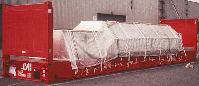
Example: Unknown plant part on a 40' flatrack
 |
||
| Plant part on 40' flatrack | ||
 |
 |
|
| Securing with tie-down lashings | ||
The type of cargo and its weight are not known. It can definitely be assumed that the six fitted tie-down lashings made from webbing cannot constitute adequate cargo securing. They have been only very slightly pretensioned and could not therefore produce frictional forces of sufficient magnitude. The single-use webbing belts have been pretensioned with a special tool. Subsequent re-tensioning is not possible, or only with considerable effort. All the buckle closures were on one side, i.e. it was unilaterally pretensioned. In addition, the shipping package is slightly overwidth, which rules out securing with tie-down lashing from the outset .
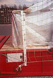
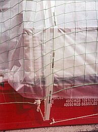
Woven tarpaulins with a net stretched over them are provided for protection against the weather; they are satisfactory but should have been secured more carefully, especially in the end wall area of the plant part.