External friction is used to refer to the resistance that is created as a result of the relative movement as the contact surfaces of two objects rub against each other. External friction is caused, in particular, by forces of adhesion and unevenness on the surfaces of the objects. Friction is virtually independent of the size of the contact surfaces. Friction is often also explained as the meshing of two materials in contact with each other at a microscopic level.
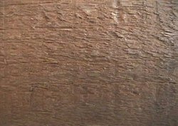 |
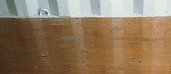
The structure of softwood on the grain edge |
This can be seen clearly, if for example, the structure of softwood is examined on the grain edge. It is not difficult to imaging that two surfaces of this nature will become 'meshed' if they are in contact with each other.
The frictional force FF is always counter to the current movement of an object. The magnitude of the frictional force is dependent on the magnitude of the normal force FN with which the contact surfaces press against each other and on the friction coefficient μ. Thus, the basic formula for Coulomb's law of friction is:
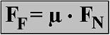
In this formula μ stands for the friction coefficient or friction factor. It is dependent on the material, the state of the surfaces (roughness and whether it is lubricated) as well as the sliding speed of the bodies rubbing against each other. The symbol used in the formula is μ, the lowercase Greek letter "m" = "mu". Different types of friction are distinguished, depending on whether or not there is relative movement between the bodies, whether the bodies are already moving and if so whether they are sliding or rolling:
- Static friction
- Sliding friction
- Rolling friction
If the conditions are otherwise identical, the static friction coefficient is always larger than the sliding friction coefficient and the rolling friction coefficient is usually much lower than the sliding friction coefficient. During frictional processes, mechanical energy is converted into heat, frictional heat.
Internal friction is due to molecular forces. It occurs when individual components of a liquid or a gas, or the various layers that make up a substance, rub against each other. The technical term is viscosity. There are two types of viscosity, dynamic and kinematic.
Contact surfaces between liquids and gases, on the one hand, and the walls of a pipe both exhibit resistance which is referred to as pipe friction.
Friction in the service of mankind. Without friction - our lives would be impossible. All forms of locomotion are ultimately reliant on friction. When transferring forces, for example, when starting or braking a vehicle or securing a load, high levels of frictional resistance are desired. All movement in gearboxes, when moving loads etc. the objective is to keep frictional resistance as low possible in order to reduce the loss of energy to a minimum.
Friction testing.In order to determine the level of frictional resistance, very simple tests can be used. The resistance to movement can be determined using measurements of force or comparisons of mass, or, measurements can be carried out to show the gradient at which an object on a slope remains in position, starts to move or remains in motion.
Test configuration used to determine frictional resistance by measuring forces:

Static friction is measured when a measuring instrument, for example, a spring balance, is pulled until the frictional force FF is almost sufficient to move the object being pressed onto the surface by the normal force FN. The force that is required to keep the object in motion and pull it across the surface corresponds to the sliding friction. When applied to a vehicle, this principle can be used to determine the rolling friction. A more detailed test can distinguish between static rolling friction and sliding rolling friction. In the field of load securing, the values for sliding friction are of most interest.
The simple method described here is not admissible for determining friction in genuine scientific studies. There are special standards which detail how friction coefficients should be determined.
Example: A block of wood with a normal force or weight-FN of 90 N is dragged over a cardboard floor. The friction coefficient FF is measured at 27 N. After transformation of the basic formula FF = μ x FN this results in:
For this example, the friction coefficient of wood on cardboard is calculated as 0.3. This value can also be expressed as 30% or three tenths. If the test block is doubled by the addition of an additional block, and increased to 180 N, then the frictional force is increased to 54 N. The frictional coefficient of 0.3 does not actually change, because 180 N divided by 54 N = 0.3. The friction coefficient remains constant for any given pair of materials.
If the normal force of an object and the friction coefficient are known, then the frictional force can be calculated mathematically. Thus, the calculation for the above example is as follows:
If the friction coefficient remains the same, the frictional force is always proportional to the normal force or weight. Thus if the normal force is doubled, the frictional force is doubled. Likewise, if the normal force is halved then the frictional force is also halved. If the friction coefficient and the frictional force are known, the basic formula FF = μ x FN can be transformed and used to calculate the normal force or weight:
 |
 |
A test configuration used to calculate the frictional resistance by comparing mass may be as follows:
 |
Sufficient weight mF is added until the mass mN only just remains motionless. When the masses start to move, weights can be removed. The formula that is used to calculate the friction coefficient and the transformed formulas based on it are:
 |
Strictly speaking, friction is still being determined using forces, since all masses are forced onto surfaces by the gravitational pull of the earth.
Example: A block of concrete with a mass mN of 200 kg is pulled over a wooden surface. The mass mF required to overcome the friction is determined to be 80 kg. In accordance with the formula μ = mF / mN this gives a friction coefficient of μ = 80 kg / 200 kg = 0.4.
If the friction coefficient and the mass of an object are known, then the required frictional force can be calculated mathematically. Thus, for the example:
- mF = μ x mN = 0.4 x 200 kg = 80 kg
- mN = mF / μ = 80 kg / 0.4 = 200 kg
 |
If no dynamometers or calibrated weights are available to determine the friction coefficient, the values can also be determined using an inclined surface. The surface is raised until the mass just starts to slide or roll. Once it has started to move, a lower angle of slope is sufficient to keep the object in motion.
There are two methods of determining the friction coefficient μ using a gradient or a sloped surface. One option is to divide the height of the sloped surface by the length of its base.
 |
 |
Example: An aluminum block is placed on a rusty steel plate which is raised at one edge. The height at a is measured at 96 cm. The length b is measured at 3.84 m. Using the formula μ = a / b, this gives a friction coefficient of μ = 0.96 m / 3.84 m = 0.25.
The friction coefficients determined using the sloped surface always correspond to the gradient of the slope expressed as a percentage. A μ value of 0.25 determined by a test such as this means that the slope has a gradient of 25%. Thus, if the friction coefficient of car tires on an icy surface is calculated at 0.1 this means that the car is able to drive on a maximum gradient of 10% on black ice.
If a pocket calculator with trigonometrical functions is available, or a table showing the values of the trigonometrical functions, then μ can be calculated using the angle of the incline. In this case the formula is:
 |
Example: Going back to the aluminum block on the rusty steel surface, the angle necessary for the block to begin to slide is 14°. The tangent of this angle is 0.25 and corresponds to the friction coefficient μ.
By transforming the formula, two known values can always be used to calculate a third unknown value:
 |
Calculating the friction coefficient μ for bulk cargo. When using a conveyor or grab to move bulk cargo, when shoveling, tipping or pouring bulk cargo, the natural slope angle or angle of repose is formed naturally.
Formation of a cargo mound with a slope angle or angle of repose of α
Using the formulas for inclined surfaces, the friction coefficients (μ values) can be calculated. The value of the friction coefficient results when the height of the heap (a) is divided by the base length of one of the flanks (b) or the tangent of the angle of repose or slope angle (α) between the slope of the heap and the horizontal plane is calculated. During testing, values are determined by leveling the surface of the contents of a receptacle and then either tipping the receptacle or placing it on a surface which is then raised at one edge until the contents start to slide/flow.
 |
Examples: A glass of salt with a level surface is tipped until the first grains of salt break from the surface. A tipping angle α of 31° is determined. The tangent of 31° can be used to determine the friction coefficient of this type of salt as μ = 0.6. A receptacle containing leveled peas is standing on a surface which is subsequently raised until the individual peas start to roll/slide. The height a = 1.36 m and the base length of the inclined surface b = 4.00 m are used to calculate a friction coefficient for peas of μ = 0.34. Checking using the measured tipping angle of 18.8° confirms the friction coefficient: tan 18.8° = 0.34.
To completely empty bulk containers on vehicles at tipping points, the loading platforms must be raised so that the "tipping angle" α is reached or exceeded:
 |
 |
With respect to the safe transportation of bulk cargoes, particular attention should be paid to the fact that loads are leveled off before the vehicle is driven off:
 |
If this rule is not followed, the load may begin to slide and overflow at very low acceleration. The picture on the far left shows a bulk load heap left in its natural state. The next picture shows that lateral acceleration of just 0.2 g would cause the shaded portion of load to slide from the vehicle. The next picture shows a vehicle where the heap has just been leveled. With the cargo loaded in this manner, it requires a lateral acceleration force of 0.6 g to make the cargo slide. The gradient which corresponds to 0.6 g is shown in the picture on the far right. The angle α is identical to the slope angle α of 31°.
The angle of repose, slope angle or discharge angle as well as the friction coefficients of bulk cargo are all affected to a great degree by the moisture content of the cargo, the size of the grains and other similar factors.
Test observations. Running tests and noting the measured data for different materials and masses or objects with varying weights will allow the following conclusions:
Bearing area. Insofar as the objects do not press into the surface, the dimensions of the bearing area have no influence on the magnitude of the friction resistance.
Weight/mass. Under otherwise identical circumstances, the friction resistance of objects is proportional to their mass/weight. Thus, doubling the mass will double the friction resistance, and halving the mass will halve the friction resistance, etc.
Material. The materials which are in contact are what determine the values observed. The magnitude of the friction coefficient depends solely on which materials are making contact.
Units of measurement when using the basic formulas. For all calculations using the basic formulas μ = FF / FN, μ = mF / mN and μ = a / b it is not relevant which unit of measurement is used to measure force, mass or distance. The important thing is that they are used consistently. Since the calculation dimensions in the formula cancel each other out, μ is a dimensionless numerical value.
Units of measurement when using the transformed formulas. With these calculations, care must be taken to ensure that the same mathematical dimensions are used, otherwise the results will not be suitable for comparison or will need to be converted. Writing down the mathematical dimensions guarantees the correct results, because errors can be spotted immediately.
Sliding friction coefficients.For load securing, the sliding friction coefficients are of particular importance. The following table contains sliding friction coefficients for selected general and bulk cargoes as well as a number of materials that are used on a regular basis. The values are taken from our own tests. The abbreviation FE mat stands for friction-enhancing mat.
| Table 1a - Sliding friction coefficients for selected materials | ||||
| Material pairs | Friction coefficient μ as | Discharge angle |
||
| Surfaces in contact or bulk cargo | Decimal |
Fraction | Gradient |
|
| Stones/loose soil, certain varieties of ore and coal | 1 | 1/1 | 100% | 45° |
| Friction-enhancing mats or car tires/very rough concrete, FE mat on FE mat (gum) | 0.9 | 9/10 | 90% | 42° |
| FE mat/rough concrete, rough wood or rough chipboard; tire rubber/macadam; certain types of paper/FE mats | 0.8 | 4/5 | 80% | 38.7° |
| FE mat/rusty steel or matt varnished wood, tire rubber on rough materials | 0.75 | 3/4 | 75% | 36.9° |
 |
 |
|
| Material with a μ value of approximately 0.8 | Material with a μ value of approximately 0.7 |
Materials of this type are ideal for use as interlayer dunnage when layering goods that are unitized with suitable strapping.
They are less suitable for use as underlay or interlayer dunnage for unsecured loads or partial loads. As vibrations occur, the friction coefficient drops dramatically and the items will start to move. These relatively thin materials tend to wear easily. At times, particularly if they are heated, these materials can even have an adhesive effect which can depreciate the value of sensitive goods.
| Table 1b - Sliding friction coefficients for selected materials | ||||
| Material pairs | Friction coefficient μ as | Discharge angle |
||
| Surfaces in contact or bulk cargo | Decimal |
Fraction | Gradient |
|
| Rough galvanized sheets, rough ekki (Azobé) or softwood/FE mat; very rough concrete or stone/very rough concrete, FE mat (gum)/wood or PE | 0.7 | 7/10 | 70% | 35° |
| FE mats or rough stones or concrete/rough wood, planed oak or smooth plywood/FE mat; very rusty steel/very rough wood; car tires/wet road; various cereals as bulk cargo | 0.6 | 3/5 | 60% | 31° |
| FE mat/PA; rough concrete or rough stones/rough wood, very rough concrete/rough concrete, various materials/FE mats | 0.5 | 1/2 | 50% | 26.6° |
 |
 |
|
| Materials with a μ value of approximately 0.6 | ||
These materials can be used to maintain friction coefficients of approximately 60%. The material on the left is available in a number of different thicknesses, but usually 6 mm and 10 mm thick. The thicker version is preferable for use with heavier goods because it doesn't wear quite so quickly. Materials of this sort are usually composite materials from rubber scrap and recycled rubber etc. The material on the right is just 2 mm thick and has a ridged surface. This is more suitable for forming unit loads.
In some cases, friction-enhancing materials cannot be brought into the containers, because they would hinder the normal work. This method can only really be implemented if the goods can be placed cleanly on prepared pads or strips. This method can also be used when loading open top containers or platform containers where the intended positions are easily accessible to staff and equipment. The use of non-slip materials is impossible if the length or any other characteristic of the load requires it to be pushed into the container.
| Table 1c - Sliding friction coefficients for selected materials | ||||
| Material pairs | Friction coefficient μ as | Discharge angle |
||
| Surfaces in contact or bulk cargo | Decimal |
Fraction | Gradient |
|
| Aluminum profiles/FE mats; | 0.45 | 9/20 | 45% | 24.2° |
| Rough wood/matt varnished wood; aluminum/FE mat; rusty steel/very rough softwood or oak; certain types of paper/PE; very rusty steel/very rusty steel; concrete/wood; concrete/concrete; minimum value for FE mats | 0.4 | 2/5 | 40% | 21.8° |
| Rough wood/wood; rough wood/PE; aluminum/softwood or PE; rusty steel/rough wood; rough galvanized steel plate/softwood; certain types of paper/cardboard or wood; concrete/wood; wood/wood; wood/special plastic films; car tires on snow | 0.3 | 3/10 | 30% | 16.7° |
| Matt varnished wood/PE; rough chipboard/softwood; rough chipboard/PE; planed ekki (Azobé)/softwood; plywood/softwood; paper/wood; steel/aluminum | 0.25 | 1/4 | 25% | 14° |
| Softwood |
In practice, dry softwood should not be calculated with a friction coefficient greater than 30%.
| Table 1d - Sliding friction coefficients for selected materials | ||||
| Material pairs | Friction coefficient μ as | Discharge angle |
||
| Surfaces in contact or bulk cargo | Decimal |
Fraction | Gradient |
|
| Planed oak, PA/softwood, PE; Bongossi, plywood/PE; FE mat/sanded wooden loading platform; rusty steel/PE, PA; rough galvanized steel/PA; contaminated steel/aluminum; dusted steel/ rough wood; wood, cardboard on textured coated board, PVC, plastic coated wooden floors etc. | 0.2 | 1/5 | 20% | 11.3° |
| PA/PE, rough galvanized steel/PE; rough wood/sanded wooden loading platform | 0.15 | 3/20 | 15% | 8.5° |
| Aluminum, PA, PE, steel, wood and various other materials on heavily sanded or contaminated FE mats; smooth steel on smooth steel; tires on ice | 0.1 | 1/10 | 10% | 5.7° |
| Water, oil and other liquids | 0.0 | 0/∞ | 0% | 0° |
 |
Normal container floor |
With normal container floors made of plywood or textured coated board, a maximum friction coefficient of 20% can be reckoned with. Even if the floor has been steam cleaned and dried thoroughly, when packers walk/drive across the floor, dust and other contamination is usually deposited thus lowering the friction.
Factors which alter the friction coefficients. The values given are just guidelines. Strictly speaking, each shipper should themselves determine the values that should be used in their situation. But beware: The values obtained under laboratory conditions are rarely the same as those that occur in practice. External influences, such as humidity, dust and grease can affect the figures considerably. Dirty loading areas with the remains of granular materials, such as sand, etc. reduce the friction coefficient considerably. Some of these values are given in table 1. The friction coefficient can, in particular, be reduced considerably by vibration, and in a worst case scenario it may even be reduced to values approaching zero.
 |
Ultra-smooth container floors |
When using containers with very smooth floors, it is recommended not to rely on friction, but instead to pack and secure the load in such a way that it cannot move, even without friction.
VDI 2702. Guideline VDI 2702, published by the Verein Deutscher Ingenieure, and entitled "Ladungssicherung auf Straßenfahrzeugen - Zurrkräfte" (Load securing on road vehicles - Lashing forces) gives the following sliding friction coefficients:
| Table 2a - Sliding friction coefficients in accordance with the VDI Guidelines | |||
| Material | Dry | Wet | Greasy |
| Wood on wood | 0.20 - 0.50 | 0.20 - 0.25 | 0.15 - 0.05 |
| Metal on wood | 0.20 - 0.50 | 0.20 - 0.25 | 0.10 - 0.02 |
| Metal on metal | 0.10 - 0.25 | 0.10 - 0.20 | 0.10 - 0.01 |
The VDI Guidelines recommend using the lowest value for the sliding friction coefficient μ if in any doubt. In addition, attention is drawn to the fact that additional material pairs and environmental influences, such as dirt and ice, require that the friction coefficients should be estimated or should be determined specifically by testing.
The following table gives sliding friction coefficients from the VDI guideline expressed as fractions, as gradients in% and as angles:
| Table 2b - Sliding friction coefficients in accordance with the VDI Guidelines | |||||||||
| Material | Dry | Wet | Greasy | ||||||
| Wood on wood | 1/5 through 1/2 | 20% through 50% | 11.3° through 26.6° | 1/5 through 1/4 | 20% through 25% | 11.3° through 14° | 3/10 through 1/20 | 15% through 5% | 8.5° through 2.86° |
| Metal on wood | 1/5 through 1/2 | 20% through 50% | 11.3° through 26.6° | 1/5 through 1/4 | 20% through 25% | 11.3° through 14° | 1/10 through 1/50 | 10% through 2% | 5.7° through 1.15° |
| Metal on metal | 1/10 through 1/4 | 10% through 25% | 5.7° through 14° | 1/10 through 1/5 | 10% through 20% | 5.7° through 11.3° | 1/10 through 1/100 | 10% through 1% | 5.7° through 0.57° |
Here it should be noted that the issue of friction is under review by the Verein Deutscher Ingenieure and the figures given above are now obsolete (information as at the beginning of 2002).
Rolling friction coefficients are much lower than static or sliding friction coefficients. Values for common materials are shown in the following table:
| Table 3 - Rolling friction coefficients of selected materials | ||||
| Material pairs | Friction coefficient μ as | Overflow angle | ||
| Surfaces in contact or bulk cargo | Decimal | Fraction | Gradient | |
| Roundwood, rollers and wheels on an unmade surface | 0.5 | 1/2 | 50% | 26.6° |
| Roundwood on rough surface | 0.2 | 1/5 | 20% | 11.3° |
| Roundwood on asphalt, steel or other firm surface | 0.1 | 1/10 | 10% | 5.7° |
| Wheels with air-filled tires on a firm surface | 0.02 | 1/50 | 2% | 1.15° |
| Steel wheels traveling on rails with flanged wheel grooves, starting and pushing on free tracks | 0.01 | 1/100 | 1% | 0.57° |
| Railroad wheels on free tracks, or clean flanged wheel grooves | 0.0025 | 1/400 | 0.25% 2.5‰ |
0.14° |
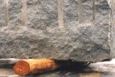
Squared lumber with a square cross-section can act like rollers. This risk is particularly high when using waney edge squared lumber since this often behaves in a similar way to roundwood.
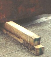
Never stand rectangular beams on edge. Rectangular formats or, better, planks should be used flat. The thickness should be calculated in order to ensure that lifting gear or ground conveyors are able to handle the goods. A better format is the so-called "sandwich" which combines wood with top-quality friction-enhancing mats glued or screwed to each side. The gluing or screwing can be made more durable if the lumber is shaped to accommodate the mats. The depth should be measured in such a way that even when a heavy load is placed on the mat, the FE material is not crushed to such an extent that the goods are resting on the wood.
 |
 |
|
| Incorrect, and incorrectly used lumber dunnage |
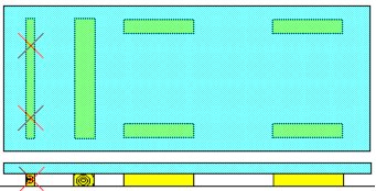
If transport jolts are to be expected transversely to the orientation in which they are laid, rectangular formats such as planks are to be used. It would be better to set out the beams parallel to the expected direction of the jolts, but for handling reasons, this is only rarely possible.
 |
|
| Risk of rolling with incorrect and correct use of wooden dunnage |
As has already been mentioned, frictional forces can be reduced to zero as a result of vibration. A certain minimum amount of load securing should always be implemented to counteract the effects of vibrations. Goods should never be transported unsecured just because the calculated or assumed friction coefficients are greater than the horizontal acceleration that is to be expected. With very few exceptions, for example, when materials are not compatible or the selected handling methods do not permit the use of friction enhancing mats, friction should always be enhanced as much as possible by selecting the appropriate materials. Since the use of tensioning or lashing aids or vertical bracing creates additional frictional forces, the load securing outlay may be reduced considerably if high friction coefficients can be achieved.