 |
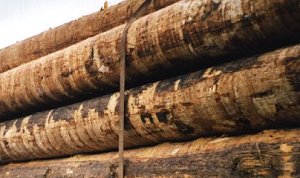
Logs |
 |
 |
|
| Long edge/with the grain | End grain/ across the grain |
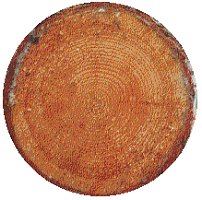
Wood is indispensable as a load securing material. A distinction is always made between the long and the short side of the wood (across the grain and with the grain). Wood is less able to withstand loads on its long edge, i.e. when the load is perpendicular to the grain. The extraction resistance of nails and screws, however, is higher when they are nailed or screwed perpendicular to the grain. In contrast, wood is far better able to withstand loads applied on the end grain, i.e. parallel to the direction of the grain.
 |
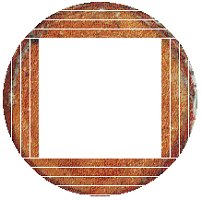 |
Untrimmed edge boards or waney edge lumber are often cut from the outer sections of a log for use as wooden dunnage.
 |
|
| Wooden dunnage board |
 |
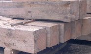
Depending on the thickness of the trunk, balks, squared lumber, battens, laths, planks and boards are cut from the trunks.
 |
 |
|
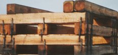
| Balks | cross-stacking of balks (with errors, in this case: no overhang, dogs attached incorrectly) |
Balks have very large cross-sections, with edges usually over 15 cm long, squared lumber starts as of about 8 cm x 8 cm.

| Solid wood |
Halved lumber |
Quartered balk |
1:2 format |
On solid wood, the heart, medulla or pith is located in the center, on halved lumber on the side and on quartered lumber on one corner. 1:2 can be a size such as 16 cm x 8 cm. Dimension stock could, for instance be 6.3 cm x 7.5 cm (2 1/2" x 3"). Thicker battens might be 3.2 cm x 5 cm (1 1/4" x 2") or 3.8 cm x 6.3 cm (1 1/2 x 2 1/2").
 |
 |
|
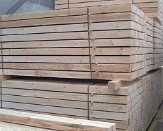
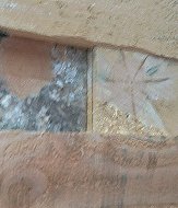
| Sticked squared lumber packages | Mold on lumber which has not been sticked |
Thin laths are used as an intermediate layer between lumber so ensure that it does not develop mold or rot.
| Very knotty waney edge lumber |
Wood with a very high frequency of knots should not be used for bracing. It must be rejected beforehand.
 |
|
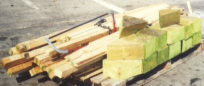
| Squared lumber, battens and wedges - Wood which has been stained indicates that it has been treated to protect it against the sirex wasp . |
The following rules of thumb can be applied to sound lumber to calculate the maximum securing load:
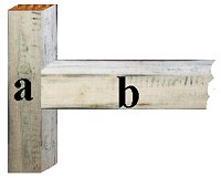 |
Applying the rule of thumb to compressive strength parallel to the grain of the wood |
Assuming that the contact surface between a and b is 10 cm x 10 cm = 100 cm², a securing force of 3,000 daN (30 kN) can be introduced via a and transmitted to b.
The following rule of thumb applies for the maximum securing load parallel to the grain:
| Softwood used for bracing, compression strength parallel to the grain, MSL = 100 daN per cm² |
Note: For road and rail transportation only, 200 daN/cm² can be assumed for the load parallel to the grain, since it is assumed that only isolated or few load events occur during each transport operation. For maritime transport, the IMO halve these values to 100 daN/cm² due to the constantly changing stresses in rough seas.
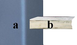 |
Applying the rule of thumb to compressive strength parallel to the grain |
Assuming that the contact surface between the steel component a and the wood b is 10 cm x 10 cm = 100 cm², a securing force of 10,000 daN (100 kN) can be transmitted between a and b.
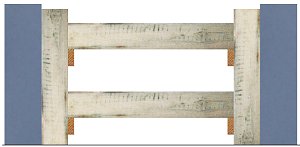 |
High outlay - low strength |
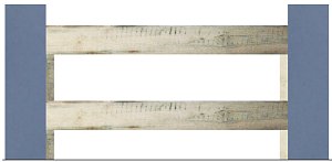 |
Little material - high strength |
Since the grain side is crucial for the bracing shown in the left-hand illustration, four horizontal bracing elements measuring 10 cm x 10 cm will achieve an MSL of 12,000 daN. The values for the load on the end grain can be used for the bracing shown in the right-hand illustration. An MSL of 40,000 daN is achieved with significantly less outlay in terms of work and materials.
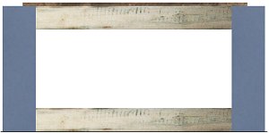 |
Even less material - high strength with four horizontal bracing elements used in pairs |
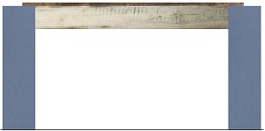 |
It may be that one pair of bracing elements may be sufficient. |
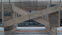
The traffic light really ought to be "double-green" for the figure at the top, since 40,000 daN is achieved with even less material. Probably, even the variant with only two bracing elements would suffice as shown in the bottom figure (the second bracing element is hidden by the first). Even this achieves 20,000 daN. The wood should be placed at the top for goods that are likely to topple. It can be placed at the bottom for flat goods which are not likely to topple. The bracing elements must be cross-braced against shifting so that they do not become detached.
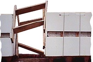 |
Unprofessional bracing which has become detached due to lack of cross-bracing |
 |
 |
|
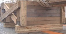
| Heavy drive shaft on trestles | ||
If the circular segment on which the wooden-clad drive shaft is placed is 50 cm wide and the wood on the trestle is 20 cm wide, there will be a projected area of 1,000 cm², which means a total bearing surface on the trestle of 2,000 cm². Since the compression load is perpendicular to the grain, the trestle can absorb 2,000 cm² x 30 daN/cm² at this point, i.e. 60,000 daN. Since the shaft has been placed on several trestles, they have obviously been over dimensioned here. The workmanship also leaves something to be desired. There is still some potential for rationalization here.
 |
|
| Securing with diagonal stays |
Lumber measuring 10 cm x 12 cm has been used here. This would produce an area of 120 cm² at the contact points. Since two pieces of wood were used as bracing on each side, the total area is 240 cm² per side. The stays would therefore theoretically absorb 240 cm² x 100 daN/cm², i.e. thus 24,000 daN. There is however a slight problem here: The stanchions are not as wide as the lumber.
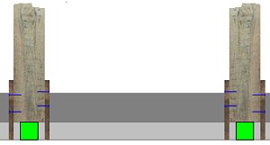 |
Always take note of to the smallest contact surfaces! |
Since the stanchions are only 8 cm wide, only an area of 8 cm x 12 cm = 96 cm² per wooden element can be used for calculation, i.e. 192 cm² per pair of stays. In reality, therefore, the stays can only be loaded with 19,200 daN per pair.
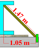 |
Only the lateral component is effective against tilting. |
Since the total length of the stay is 1.47 m and the transverse component is calculated as 1.05 m, a pair of stays secures the beam against tilting with 1.05 m / 1,47 m x 19,200 daN = 13,714 daN.
Generally, the following rules apply:
- If it is feasible, always brace horizontally;
- If it is feasible, brace so that the end grain loading capacity is used;
- Always brace against the parts with the greatest load-bearing capacity, e.g. on cases, use the plate effect provided by the base and lid or guide the forces into the vertical sides.
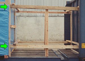 |
Transferring forces onto the ends of the side walls of the box |
 |
|
| Chamfered wood (a) - wood cut to a bevel (b) |
Securing measures of this kind can only be created using wooden aids and driving wedges, which are removed again after securing has been completed.
 |
|
| Driving wedges - tapered blocks - slim wedges |
Driving wedges can be used individually or in pairs. They should be made of hardwood. The very shallow angle here produces large leverage effects which can be used to achieve extremely high forces. Caution is therefore demanded. Only drive wedges in gently and then fix them into place.
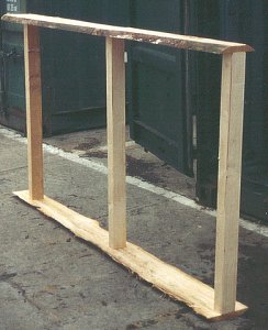 |
Simple stays for filling gaps which can be prepared outside the container |
Sometimes only very simple structures are required to fill in a gap in the container. But one last note: The less material has to be used for load securing the better. The best and most cost-effective load securing measure is a compact stow using well-protected and sufficiently strong packages.