Working and general stowage plans are prepared and used in normal maritime transport. The same practice should be adopted when packing other cargo transport units.
The CTU guidelines even make this an obligation: Section 3.1 of the CTU guidelines deals with actions required before packing. The following are some of the points defined in the guidelines:
| 3.1.4 |
Packing should be planned before it is started. This should make it possible to segregate incompatible cargoes and produce either a tight or secured stow, in which the compatibility of all items of cargo and the nature, i.e. type and strength, of any packages or packaging involved are taken into account. The possibility of cross-contamination by odor or dust, as well as physical or chemical compatibility, should be considered. |
This point gives some fundamental guidelines as to basic stowage methods. Corresponding explanations and illustrations are provided in section 4.2.4 in this Container Handbook.
 |
 |
 |
 |
| |
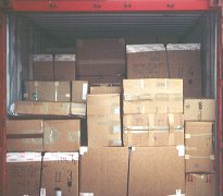
Not packed tightly and securely! |
|
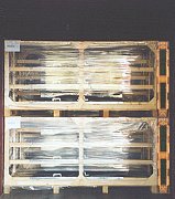
Packed tightly and securely |
| 3.1.5 |
The planned cargo should not weigh more than the maximum payload of the CTU. In the case of containers, this ensures that the permitted maximum gross weight of the container (which includes the payload) marked on the CSC Safety Approval Plate will never be exceeded (see also Annex 3). For CTUs not marked with their maximum permissible gross weight, tare weight or any other features, any of these values should be known before packing starts. According to CEN standards, a swap-body of class C (7.15 m to 7.82 m) will have a maximum gross mass of 16,000 kg and a swap-body of class A (12.0 m to 13.6 m) will have a gross mass of up to 32,000 kg. |
|
 |
 |
| |
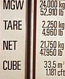
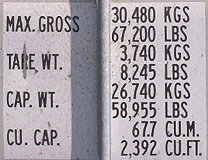
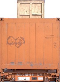
Information on a 20' and a 40' container |
Annex 3, which is referred to under this point, deals with the consequences of overloading CTUs. Precise planning of packing is indispensable. Planning becomes even more important when the amount of the load to be packed is sufficiently large, in that it ensures that the containers are utilized to their maximum in terms of space and weight. This is the only way to minimize transport costs. A detailed packing plan is indispensable for this.
The volume-to-payload ratio of the containers can be determined from their volume and payload information, which can be obtained beforehand from prospectuses or documents provided by the container owners. The volume-to-payload ratios for the containers shown are calculated as follows:
20' container = 33.5 m³ / 21.75 t = 1.54 m³/t
40' container = 67.7 m³ / 26.74 t = 2.53 m³/t
This means that for every metric ton of payload on the 20' container, 1.54 m³ of packing space is available, and on the 40' container there is 2.53 m³ available per metric ton of cargo mass. The volume-to-payload ratio of a transport container therefore answers the question "How many cubic meters of stowage volume are available per metric ton of payload?"
The dimensions and masses of the items to be loaded can be used to determine the stowage factor of the load. Assuming that a consignment of 200 metric tons is to be loaded: The volume of the items is calculated to be 440 m³. The net stowage factor of the cargo is calculated by dividing the cargo volume by the cargo mass. Net stowage factor of the cargo = 440 m³ / 200 t = 2.2 m³/t. This means that, if the load is packed with no wasted space, a volume of 2.2 m³ would be required for every metric ton of cargo. Since most loads are not 100% suitable for modular packing, certain losses will result from stowage or packing. Experienced practitioners can estimate these losses well or know from their own records what values are to be taken for calculation purposes. This information can also be obtained from relevant specialist literature. For our example, let us assume stowage loss of 10 %. The gross stowage factor will then not be 2.2 m³/t but in fact 2.42 m³/t. Experts also say: "Cargo is stowed by a factor of 2.42". A comparison with the volume-to-payload ratios of the containers immediately reveals that economical transport can only be expected with the 40' containers.
If a consignment of 300 m³ volume and 230 t mass were waiting for loading and it were known that 15% stowage loss is to be expected, the net stowage factor of the cargo would be 300 m³/ 230 t = 1.30 m³/t and the gross stowage factor 1.5 m³/t. In this case, experts would say: "Cargo is stowed by one and a half times" or: "Cargo is stowed by a factor of 1.5". By comparing the numeric values, it can immediately be seen that only 20' containers can be considered for economical transportation.
Other aspects must of course still be considered, such as factors relevant to a particular transport route or to the destination countries, etc. These points are dealt with in the following and other sections of this Handbook. Notes can also be found in the CTU guidelines:
| 3.1.6 |
Notwithstanding the foregoing, any height or weight limitation along the projected route that may be dictated by regulations or other circumstances (such as lifting gear, handling equipment, clearances and surface conditions) should be complied with. Such weight limits may be considerably less than the permitted gross weight already referred to. |
| 3.1.7 |
Stowage planning should take account of the fact that CTUs are generally designed and handled assuming the cargo to be evenly distributed over the entire floor area. Where substantial deviations from uniform packing occur, special advice for preferred packing should be sought. |
This applies indirectly to the line load of containers. This is determined by dividing the payload of the containers by a calculation length. For 20' containers, this calculation length is 2 m less than the container length, for 40' containers 3 m less. It can also be expressed as follows: In order to obtain the calculation length, 1 m is subtracted from each end for 20' containers and 1.5 m from each end for 40' containers.
|
 |
Determining the calculation length for the line load for 20' containers |
|
 |
| |
Determining the calculation length for
the line load for 40' containers |
The payload, maximum gross weight (MGW), net, capacity weight (CAP WT) or whatever is specified on the container as the permissible payload, is divided by the relevant calculation length. The result is the permissible line load.
 |
 |
| divided by |
|
 |
 |
| equals |
|
| for the 20' container |
for the 40' container |
| a permissible line load of: |
|
 |
 |
It must be noted that the payload should actually be given in Newtons and the line load in Newtons per meter or daN/m or kN/m, if the line load is assumed to be a force. If the line load is regarded as a "line mass", the units kilogram per meter or metric tons per meter would be completely correct.
For older 20' containers with a payload of around 18,000 kg, the permissible line load is this around 4.5 t/m, while for older 40' containers with an average payload of 27,000 kg it is -3.0 t/m. On more modern containers, the values are considerably higher: On some 20’ containers, as much as 6.75 t/m. If necessary,
the current values must be determined for every loading operation.
| 3.1.8 |
When a heavy, indivisible load is to be shipped in a CTU, due regard should be given to the localized weight-bearing capability of the unit. If necessary, the weight should be spread over a larger area than the actual bearing surface of the load, for example by use of properly secured baulks of timber. In such a case the method of securing the load should be planned before packing is started and any necessary preparations should be made. |
For instance, a machine part weighing 20 t and 3 m long could not simply be loaded into the 20' container described above without additional measures being taken. There would be a danger of it damaging the container floor.
 |
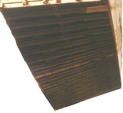 |
Container floor
seriously deformed
due to overloading |
The machine part used as an example (20 t weight, 3 m long), exerts a load of 6.666 metric tons per running meter. This is calculated by dividing 20 t by 3 m. Since forces are involved, a correct calculation would have meant dividing the normal force of 19,620 N by the length of 3 m. This would have produced the correct values of 65,400 N/running meter, 6,540 daN/running meter or 65.4 kN/running meter. Comparison with the permissible line load of the container of 5,437.5 kg/m (5,334.2 daN/m or 53.342 kN/m) immediately reveals that loading cannot be carried out unless additional measures are taken.
|
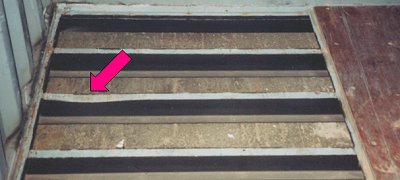 |
| |
Bottom cross members of a container deformed due to
overloading |
In this example, this means that the weight of the case has to be distributed over a larger number of bottom cross members. This can be achieved by laying squared lumber longitudinally across them. The required length of the squared lumber is determined by dividing the weight of the case (or more correctly the "normal force") by the permissible line load of the container. In the example, this would be 20,000 kg divided by 5,437.5 kg/m = 3.68 m ( 19,620 daN / 5,334.1875 daN/m = 3.68 m).
|
 |
| |
Non-permissible loading of 20 t machine box: Line load
too great |
|
 |
| |
Permissible loading with appropriate line load |
An older model of container would not have been permitted to be used for transport, due to its low permissible payload of 18,000 kg. A more modern model of container with a payload of 24,000 kg has a line load of 6 t/m. The box could be loaded into a container of this kind without requiring any further measures. If the box is to be loaded with very very light but bulky items in the 40' container in the example, the following calculation would need to be made: 20,000 kg / 2,971.1 kg/m = 6.73 m. In the 40' container described, the box would have to be placed on squared lumber which was at least 6.73 m long. As far as practical considerations are concerned, it should be noted that where possible squared lumber with a large vertical edge length should be used, e.g. 8 cm x 16 cm or 10 cm x 20 cm etc. Half-sizes of this kind are generally less expensive. However, since there is a danger of them collapsing, they must be braced firmly laterally to prevent tilting. Preferably, this should result in a wooden lattice with a large height.
| 3.1.9 |
If the planned cargo of an "open topped" or "open sided" CTU will project beyond the overall dimensions of the unit, special arrangements should be made. It should be borne in mind that road traffic regulations may not allow such overhangs. Furthermore, CTUs are often loaded door-to-door and side by side, thus not permitting any overhang. |
|
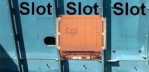 |
Photographic representation: Flatrack with overhang on both sides in the cellguides of a ship |
It can clearly be seen from this photographic representation that three slot rates must be paid for transport, since the two adjacent slots on the ship must be kept free.
|
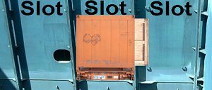 |
Photographic representation: Flatrack with overhang on one side in the cellguides of a ship |
If the center of gravity of the flatrack makes it technically possible to load it with an overhang on one side and it is also possible to load it in this state on the ship - after agreeing this with the shipping company - , only two slot rates will have to be paid.
|
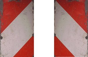 |
Marking for overwidth loads for road transport |
Overwidth road vehicles must be marked with red and white, diagonally striped plates.
|
On board the ship, overheight flatracks can only be stowed as the uppermost container either in the hold or on deck. Ships with flaps can segregate individual stowage areas from others and could also store the flatrack in another position. As one slot must be kept free above the flatrack, two slot rates must also always be paid. |
 |
|
Overheight flatrack |
| 3.1.10 |
The center of gravity of the packed cargo should be at or near the longitudinal center-line of the CTU and below half the height of the cargo space of the unit. (see also 3.2.5 and other relevant sections.) |
|
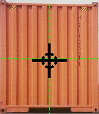 |
Prescribed center of gravity
for loaded containers |
| 3.2.5 |
The weight of the cargo should be evenly distributed over the floor of a container. Where cargo items of a varying weight are to be packed into a container or where a container will not be full (either because of insufficient cargo or because the maximum weight allowed will be reached before the container is full), the stow should be so arranged and secured that the approximate center of gravity of the cargo is close to the mid-length of the container. If it is not, then special handling of the container may be necessary. In no case should more than 60 % of the load be concentrated in less than half of the length of a container measured from one end. For vehicles, special attention should be paid to axle loads. |
|
 |
| |
Ideal load distribution in a container with a payload of
18,000 kg |
|
 |
| |
Maximum permissible weight shift for containers |
If necessary, the real center of gravity of the container must be determined by calculating its moment.
| 3.1.11 |
When planning the packing of a CTU, consideration should be given to potential problems which may be created for those who unpack it, e.g. cargo falling when doors are opened. |
|
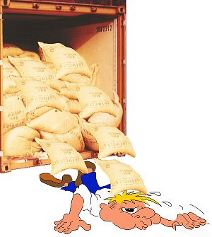 |
Danger to persons due to badly packed containers
|
This cartoon figure appear amusing, but in the real world, dreadful incidents have occurred. To cite only one accident here: Cotton bales weighing around 220 kg falling out onto a worker injured him so severely that he suffered serious fractures to his spine and hip in addition to internal injuries to vital organs. The young man only survived thanks to immediate medical attention and a number of operations. For the rest of his life, he is now confined to a wheelchair. And all this simply because the cotton bales in the container were badly packed and not secured.
| 3.1.12 |
Before a CTU is packed, it should be ensured that the personnel responsible for the packing are fully informed about all the risks and dangers involved. As a minimum requirement some sketches showing the basic rules of CTU packing should be available. The present Guidelines should also be readily available. If necessary, the shipper and the packing personnel should consult each other regarding any special feature of the cargo to be packed into the units. In particular, information on possible dangerous cargoes should be considered very carefully. Consideration should also be given to the provision of appropriate training for personnel involved in packing CTUs. |
Data sheets with a plan view and/or side view of different containers, in which the items to be packed are drawn in to scale, should be provided for planning packing.
|
 |
| |
Blank form for a packing plan |
|
 |
| |
Blank form for a packing plan with dm² grid |
|
 |
| |
Blank form for a packing plan with dm² or cm² grid |
The actual design of the packing plans is of little significance. What is crucial is that they contain all the most important information, e.g. the interior dimensions of the container, and that the stowage plan can also provide important evidence in the event of any subsequent (legal) disputes.
When planning packing and illustrating it in the forms, the following points must be considered: How are an even load along the floor and an acceptable center of gravity to be achieved? What goods will have to be brought in using a fork-lift truck? Will any other ground conveyors need to be used? Is manual handling necessary - or even desired? Do all items have a sufficient loading capacity? Can they be stacked? Will items have to be packed on top? Can the necessary basic stowage rules be met for all items? Are dangerous cargoes also to be loaded? Has unloading also been considered? And so on.
It should be checked whether the stowage factor of the cargo has previously been determined using the weights and dimensions of the cargo and compared with the volume-to-payload ratio of the container. This is always good practice; moreover, this procedure gives all less experienced staff an insight into what is feasible. It goes without saying that the maximum payload of the container must not be exceeded.
| 3.1.13 |
When packing a CTU, the shipper and persons responsible for packing should bear in mind that any failure to pack and secure the cargo correctly may result in additional costs that they will have to bear. If, for example in railway transport, a unit is found not to be properly packed and secured, the rail-car may be marshalled out of the train into a siding and the transport can only be continued once the cargo has been properly secured. The shipper may have to pay for this work, especially for the repacking and resecuring operation, as well as for the additional time during which the rail-car has been used. In addition, he may be held responsible for any delay of the transport operation. |
| 3.1.14 |
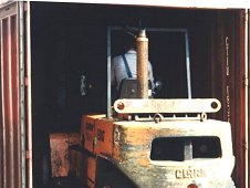
Not all handling equipment is suitable for container packing. Lift trucks used for container packing and unpacking should have a short lifting mast and a low driver's overhead guard. If the lift truck operates inside the container, equipment with electric power supply should be used. Container floors are built to withstand a maximum wheel pressure corresponding to an axle load of a lift truck of 5,480 kg or 2,730 kg per wheel. Such an axle load is usually found on lift trucks with a lifting capacity of 2.5 t. |
The short lifting mast and low driver's overhead guard alone do not say anything about the usefulness of the fork-lift truck. If these values are less than the height of the door, the fork-lift truck container can de driven into the container, but it is not automatically clear whether load can be stacked. This is where free lift is crucial. The higher the forks can be lifted without changing the total height, the more suited the fork-lift truck is for stacking and working in the container.
More information is provided on axle loads and working with fork-lift trucks in other sections of this Handbook.
|
 |
 |
| |
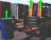
Fork-lift truck with a large free lift for loading box containers |
| 3.1.15 |
If the CTU floor is at a different height level than the loading ramp, a bridging unit may need to be used. This may result in sharp bends between the loading ramp and the bridging unit as well as between the bridging unit and the CTU floor. In such cases the lift truck used should have sufficient ground clearance to ensure that the chassis does not touch the ramp when passing these bends. |
|
 |
 |
| |
Sufficient ground clearance for a fork-lift truck |
|