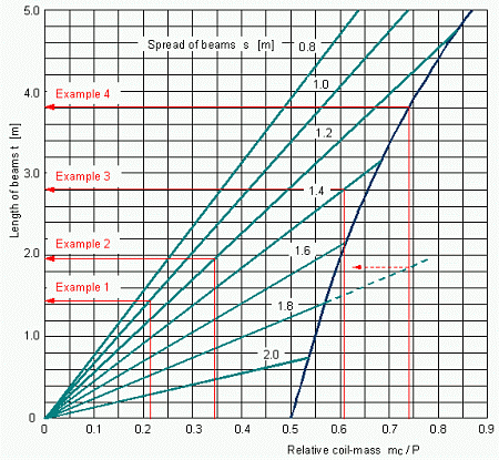
By entering with the "relative coil-mass mC/P" the diagram in Figure 13 delivers the necessary length of the beams, depending on their spread s (set of curves to the left). For coils of less than 0.5 P there is only the spread of importance.
For heavier coils, of which only one can be loaded at a time, the entry with the relative coil-mass first of all yields the minimum length t of beams necessary for safeguarding the longitudinal strength (limiting curve to the right). Only if the spread is so small that it demands longer beams, then of course the greater value applies (set of curves above the limiting curve).

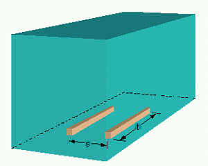
Figure 12: Spread s and length t of bedding timbers or steel beams
Example 1: mC = 6 t; P = 28 t; mC/P = 0.214; spread of beams s = 1.0 m: Necessary length t of longitudinal beams per coil = 1.45 m.
Example 2: mC = 9 t; P = 26 t; mC/P = 0.346; spread of beams s = 1.2 m: Necessary length t of longitudinal beams per coil = 1.96 m.
Example 3: mC = 17 t; P = 28 t; mC/P = 0.607; s = 1.4 m: Necessary length t of longitudinal beams = 2.80 m. For longitudinal strength a length t = 2.06 m would have been sufficient (blue curve).
Example 4: mC = 20 t; P = 27 t; mC/P = 0.741; s = 1.8 m: Necessary length t of longitudinal beams = 3.81 m. For the transverse strength with s = 1.8 m a length t of just under 1.9 m would have been sufficient.

Figure 13: Diagram for the determination of necessary bedding dimensions