 |
||
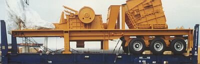
| Adequately secured concrete breaker on a 40' flatrack | ||
Once again, the manufacturer had not taken any precautions with regard to transport and cargo securing, resulting in particularly high material and labor costs when it came to securing the concrete breaker. Some areas of the vehicle could not be used for cargo securing, because they had hydraulic and electric lines running along them. Some correctly placed, appropriately dimensioned lashing points would have simplified cargo securing operations tremendously.
 |
||
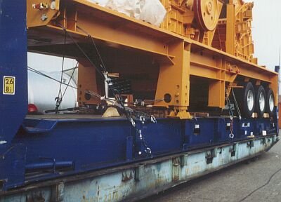
| Oblique view of some securing measures | ||
At the sharp edges of the breaker components, the maximum securing load of the wire ropes was reduced by approx. 50%, but no other fastening arrangement was possible due to the design of the breaker.
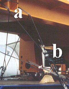 |
Lashing problems caused by the breaker design |
In order to achieve uniform lashing, quadruple cable shear should have been provided at (a) and double shear at (b). However, this was impossible because of the very narrow openings provided by the design. The length of the wires hindered manual pretensioning. As a result, a very large number of turns had already been used when it came to actual pretensioning by means of the turnbuckles.
  |
||
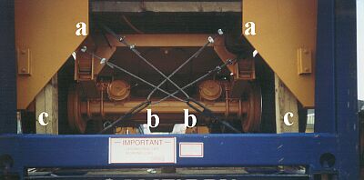
| Top and selective enlargement below: Correct arrangement of wire ropes |
||
At the rear part of the vehicle, it was possible to fit the wire ropes correctly. Quadruple shear is produced by the sharp edges at a, and double shear at the turnbuckle stirrups b. A positive feature in the Figure is the blocking up of the vehicle off its suspension by means of the squared lumber c, so preventing unnecessary vibrations of the vehicle and abrupt loading of the lashing wire ropes.
 |
||
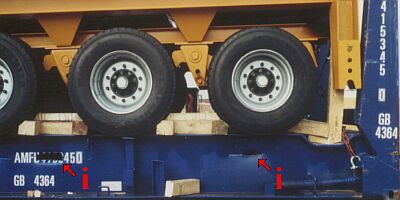
| Lengthwise securing using wedge members | ||
The wedge members, among other things, contribute to lengthwise securing of the vehicle. This effort could have been spared, if the breaker had had appropriate lashing points: adequate securing could have been quickly and cheaply achieved with oblique lashings. The misshandling of the flatrack with the tines of a forklift truck at (I) was far from "gentlemanly".
There is a knack to producing tight fitting wooden assemblies.
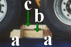 |
Wedge member bracing between the tires |
First of all, the two wedge members a are inserted crosswise between the tires on the axle. An auxiliary member, not shown here but whose length matches the gap between the members a, is cut to size, inserted between the wooden members and driven apart towards the tires with driving wedges. The then somewhat enlarged gap is measured and the wooden member b is cut to this size and fitted. Once the dimensions for the securing member c have been determined, this member is cut to size and likewise fitted. Finally, the driving wedges are knocked free and the auxiliary member is removed. The wooden bracing is held firmly in place due to the elasticity of the tires, without any nailed joints.
 |
||
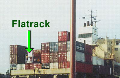
| Slot for the flatrack on board ship | ||
This picture illustrates just how important it is to secure each cargo appropriately, even in the vertical direction. The flatrack is positioned in the last bay of the ship and will experience the greatest vertical accelerations during pitching at sea, as well as the other movements of the ship.