 |
|
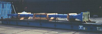
| Inadequately secured plant part |
In this instance, a lot of work and material have gone into securing which will not withstand the shipping stresses which may arise. The transverse securing consists of steel strapping, mostly fitted in the form of tie-down lashings. The nailed-down wedges which are intended to effect lengthwise securing are a waste, since they are incapable of performing their task.
 |
|
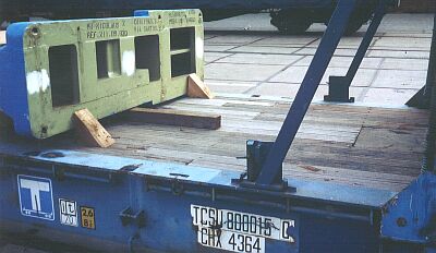
| The wedges cannot withstand the longitudinal forces which are to be expected. |
Although the item of cargo is not excessively heavy, it does nonetheless weigh 8,750 kg. A positive feature is that the wedges have been correctly cut. Nailing into the face grain is possible.
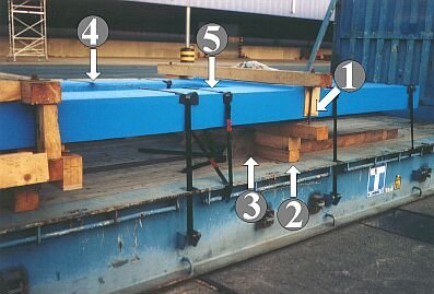 |
The item of cargo is supported under the struts (1) by crosspieces (2) which are (should be) secured by wedges (3) against tipping in the lengthwise direction. As has already been mentioned, the use of steel strapping as tie-down lashing (4) is problematic. The use of steel strapping as direct lashing (5) is better, although it was applied here in a somewhat unfavorable manner.
If it is assumed that the cargo will be exposed to the highest possible transport stresses in combined road/rail/sea transport operations, the following horizontal stresses should be expected, without taking account of frictional forces:
- lengthwise: 8,584 daN normal force at 1.0 g = 8,584 daN
- crosswise: 8,584 daN normal force at 0.8 g = 6,867 daN
 |
||
| Diagram showing the principle of appropriate securing - side view |
||
 |
||
| Diagram showing the principle of using cross-over beds as a base structure - side view |
||
Since two cross-over beds provide a total of eight cross-over points, simple wooden beams with an edge length of 6 cm would suffice for supporting the steel part from below.
 |
Cross-over bed in plan view |
 |
 |
 |
| Bracing of the narrow side of the part in side, end and plan view | ||
The variant shown is only a suggestion. Raising of the active squared lumber in the top layer can also be achieved by nailing planks to one another in steps, or by other similar methods. The other examples relating to wooden bracing contain a range of suggestions. When using two wooden members as longitudinal struts, they need to be at least 12 cm x 12 cm in size. If 10 cm x 10 cm wooden members are used, three are needed . The same minimum lumber thicknesses apply for bracing the other side.
 |
 |
|
| Bracing of the broad side of the plant part in side and plan view | ||
 |
Bracing of the broad side of the plant part in end-on view |
Appropriate transverse securing can be readily achieved using loop lashings, which are arranged around the opposite beam of the plant part from the lashing point(s), the question of whether the ends of the loop lashings are applied to one lashing point or two being dependent on the maximum securing loads of the lashing materials and points used.
 |
 |
| One lashing point per loop lashing | Two lashing points per loop lashing |
 |
||
| Arrangement of loop lashings in end-on view | ||
If the various methods are selected, the securing looks like this overall:
  |
||
| Top and selective enlargement below: Securing with wooden bracing in the lengthwise direction and two loop lashings to the sides. Loop lashing ends applied to one lashing point. |
||
  |
||
| Top and selective enlargement below: Securing with wooden bracing in the lengthwise direction and two loop lashings to the sides. Loop lashing ends applied to two separate lashing points. |
||